Rabu, 19 Desember 2012

2Tak Engine

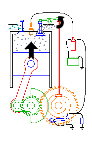
A Running Two Stroke Engine:

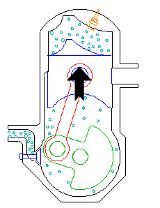
A two-stroke in its purest form is extremely simple in construction and operation, as it only has three primary moving parts (the piston, connecting rod, and crankshaft). However, the two-stroke cycle can be difficult for some to visualize at first because certain phases of the cycle occur simultaneously, causing it to be hard to tell when one part of the cycle ends and another begins.
Several different varieties of two-strokes have been developed over the years, and each type has its own set of advantages and disadvantages. The subject of the animated GIF (and this dissertation) is known as a case-reed type because induction is controlled by a reed valve mounted in the side of the crankcase.
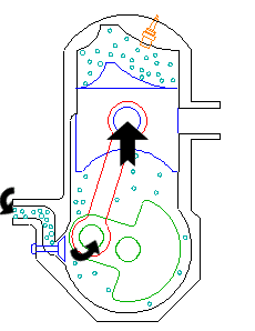
The easiest way to visualize two-stroke operation is to follow the flow of gases through the engine starting at the air inlet. In this case, the cycle would begin at approximately mid-stroke when the piston is rising, and has covered the transfer port openings:
Transfers closed
As the piston moves upward, a vacuum is created beneath the piston in the enclosed volume of the crankcase. Air flows through the reed valve and carburetor to fill the vacuum created in the crankcase. For the purposes of discussion, the intake phase is completed when the piston reaches the top of the stroke (in reality, mixture continues to flow into the crankcase even when the piston is on its way back down due to the inertia of the fuel mixture, especially at high RPM):
Top-Dead-Center
During the down stroke, the falling piston creates a positive pressure in the crankcase which causes the reed valve to close. The mixture in the crankcase is compressed until the piston uncovers the transfer port openings, at which point the mixture flows up into the cylinder. The engine depicted here is known as a loop-scavenged two-stroke because the incoming mixture describes a circular path as shown in the picture below. What is not readily apparent in the picture is that the primary portion of the mixture is directed toward the cylinder wall opposite the exhaust port (this reduces the amount of mixture that escapes out the open exhaust port, also known as short-circuiting):
Mixture Transfer
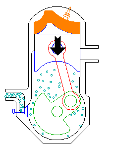
Mixture transfer continues until the piston once again rises high enough to shut off the transfer ports (which is where we started this discussion). Let's fast-forward about 25 degrees of crank rotation to the point where the exhaust port is covered by the piston. The trapped mixture is now compressed by the upward moving piston (at the same time that a new charge is being drawn into the crankcase down below):
Compression
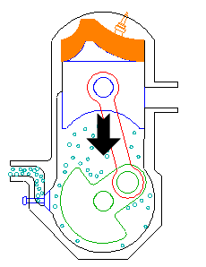
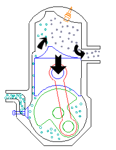
Somewhat before the piston reaches the top of the stroke (approximately 30 degrees of crank rotation before top-dead-center), the sparkplug ignites the mixture. This event is timed such that the burning mixture reaches peak pressure slightly after top dead center. The expanding mixture drives the piston downward until it begins to uncover the exhaust port. The majority of the pressure in the cylinder is released within a few degrees of crank rotation after the port begins to open:
Exhaust
Residual exhaust gases are pushed out the exhaust port by the new mixture entering the cylinder from the transfer ports.
That completes the chain of events for the basic two-stroke cycle. The discussion is not complete. The animated demonstration has an added device commonly known as an expansion chamber attached to the exhaust port. The expansion chamber (an improperly named device) utilizes sonic energy contained in the initial sharp pulse of exhaust gas exiting the cylinder to supercharge the cylinder with fresh mixture. This device is also known as a tuned exhaust.
Picking up the discussion at the point shown by the exhaust blowdown picture above, an extremely high energy pulse of exhaust gas enters the header pipe when the piston begins to open the exhaust port:
Initial Pressure Pulse
The sonic compression wave resulting from this abrupt release of cylinder pressure travels down the exhaust pipe until it reaches the beginning of the divergent cone, or diffuser, of the expansion chamber. From the perspective of the sound waves reaching this junction, the diffuser appears almost like an open-ended tube in that part of the energy of the pulse is reflected back up the pipe, except with an inverted sign (a rarefaction, or vacuum pulse is returned). The angle of the walls of the cone determine the magnitude of the returned negative pressure, and the length of the cone defines the duration of the returning waves:
Returned Negative Pressure
The negative pressure assists the mixture coming up through the transfer ports, and actually draws some of the mixture out into the exhaust header. Meanwhile, the original pressure pulse is still making its way down the expansion chamber, although a considerable portion of its energy was given up in creating the negative pressure waves. The convergent section of the chamber appears like a closed-end tube to the pressure pulse, and as such causes another series of waves to be reflected back up the pipe, except these waves are the same sign as the original (a compression, or pressure wave is returned). Notice that this cone has a sharper angle than the diffuser, so that a larger proportion of energy is extracted from the already weak pressure pulse:
Mixture Extraction
This pulse is timed to reach the exhaust port after the transfer ports close, but before the exhaust port closes. The returning compression wave pushes the mixture drawn into the header by the negative pressure wave back into the cylinder, thus supercharging (a bigger charge than normal) the engine. The straight section of pipe between the two cones exists to ensure that the positive waves reaches the exhaust port at the correct time:
Supercharging
Since this device uses sonic energy to achieve supercharging, it is regulated by the speed of sound in the hot exhaust gas, the dimensions of the different sections of the exhaust system, and the port durations of the engine. Because of this, it is only effective for a very narrow RPM range. This explains why two-stroke motorcycles equipped with expansion chambers have such vicious powerbands (especially in the old days before variable exhaust port timing existed). With the design illustrated here (i.e. a single divergent stage and a single convergent stage), the powerband of the engine will be akin to a 'light switch' - once the expansion chamber goes into resonance, there will be a HUGE, almost instantaneous increase in power. The powerband can be softened somewhat by reducing the angles on the cones, but this is simply due to a lower degree of supercharging. In order to get the best of both worlds (a large power increase and a wide powerband), the cones should consist of several sections, with a different angle for each section. Proper design of even a simple expansion chamber is somewhat of a black art, even though formulae exist that will get you in the ballpark (there is quite a bit more to this than simply choosing the appropriate angles and lengths based on sonic velocity - everything about the pipe comes into play, including the headpipe diameter and length, and the tailpipe ('stinger') diameter and length). Design of a multi-stage expansion chamber becomes incredibly difficult - it basically comes down to the old 'cut and try' approach in the end. This of course is not even considering whether or not the exhaust and transfer port timings and outlet areas have been optimized for expansion chamber use.


And last but not least a running 2 stroke engine animation:

Two-stroke animation failed to load try www.dukesofwindsoar.com/page_photos/2stroke/two-stroke_c.gif

Selasa, 18 Desember 2012

Kopling Bebek 4Tak

Setel / Setting Kampas Kopling bebek 4 tak

ni agan agan yang punya masalah di transmisi seputar kopling buat motor dengan transmisi otomatis, biasanya kopling selip, ati gigi presneling susah  mundur, biasanya kebanyakan bengkel menyarankan untuk langsung ganti kampas kopling, ya maklumlah gan biar dagangannya laku, untung tambah gede gan, tapi bagi konsumen udah kantong tipis masih ganti kopling yang indoparts saja minimal 70ribu gimana kalo yang asli bisa tidak makan satu minggu… hehehehe


kampas kopling motor bebek. type :plat basah

Nah Biar ga kejebak tuh sama bengkel2 “nakal” makanya ane kasih informasi seputar masalah tersebut, kalo ketemu masalah tersebut jangan pusing mikirin modal buat ganti kampas kopling, bisa saja cuma setelan/settingan/pengaturannya yang tidak pas.

buat cara ngesetnya putar baut pada bagian kanan blok mesin biasanya sih agak belakang dekat pengisian oli.


tu baut tumpuk 2 gan, baut kecil tengah ukur 8 itu buat setting kampas, ama murnya ukur 14 diluar buat ngancing/mengikat baut setelan biar ga muter2 lagi.

cara setetelnya:

-putar mur besar 14an kekiri hingga kendor.

-putar baut kecil (baut setelan) kearah kanan hingga mentok

-putar baut kecil kekiri sampai terasa ada sentuhan, (untuk menetralkan posisi)

-putar baut kecil kekanan antara 1/4 (seperempat)sampai 1/8(seperdelapan) putaran ini adalah inti penyetelan.


-tahan posisi baut kecil lalu kencanggkan mur besar untuk mengunci posisi baut kecil


cara test setelannya:

-standarkan ganda biar ban belakang menggantung

-putar gas 1/4 putaran sekitar mesin 1000- 2000rpm

-bila ban belakang diam (tidak berputar) berarti setelan berhasil

-bila berputar berarti setelan gagal


Nah itu gan  cara buat ngeset setelan kampas kopling, kalo disetel berulang2 gagal terus yah bawa kebengkel saja tapi siap2 puasa ya gan, berarti tu kuda besi minta diperhatiin sama agan… hehehehe Jangan Lupa Klik Iklan Disamping ini untuk donasi. Terima kasih

Ignition timing for CDI

About timing

Timing a bike refers to setting when a spark jumps the gap between the center electrode and the ground electrode on a spark plug and its relation to the rotation of the crankshaft. Adjusting when this happens is very important and can significantly affect how the bike runs.
This has been achieved by using a mechanical system called points ignition for many years. Recently, advances in electronics have introduced the CDI (Capacitor Discharge Ignition) which is what we will examine here.
Lets look at the parts of a CDI system and how they work.
  1. Flywheel (internal rotor, or external rotor) with magnets
  2. Stator plate with coils and pickup/hall sensor (as opposed to a points stator plate, which has points and a condensor)
  3. CDI box
  4. High Tension Coil
  5. Spark Plug
[edit]

Timing and CDI's

We won't go into great depths on how the CDI produces the spark, or how electricity works in general (we are only interested in getting the spark to happen at the appropriate time) but I will glance over the important parts that relate to the timing.
[edit]

The basics

The flywheel is attached to the crankshaft. When the engine is running, the flywheel spins in either a clockwise or counterclockwise direction (depending on your engine). The stator plate is attached to the engine and stays stationary while the engine is running. The stator has two main ignition components; a coil, and a hall sensor/pickup. When the flywheel spins next to the coil, the magnetic fields from the magnets produce electrical current that flows through wires wrapped around the coil. A wire attached to the stator carries this current to the CDI box which has a capacitor. The current is stored in the capacitor (a capacitor is a little like a battery) until it is ready to be sent to the spark plug to create the spark. The hall sensor detects changes in the magnetic field and sends a signal to the CDI box via a wire. This signal is created by the hall effect and it happens when the flywheel magnet changes poles over the top of the pickup (N to S, or S to N depending on the flywheel and it’s rotation). When this signal is received by the box, it discharges the capacitor and sends that electrical current to the spark plug (through the HT coil which converts the current to high voltage) and this is the point when the spark plug fires.
[edit]

Effects of timing and curves

Before we actually set the timing on a bike, lets talk about the effects of different timing, and why some CDI boxes have a curve.
Once the timing has been set somewhere around a few mm before the piston reaches top dead center the bike will run. Too far in either direction and it will run very poorly, but get it close to optimal and it will run nicely. Once it runs well, changes in spark timing have the most effect on the temperature of the gasses that exit out the exhaust port of a cylinder. What this means is that if a spark happens somewhere around 2.5mm before top dead center (BTDC), combustion will complete earlier in the cycle and have time to dissipate its heat into the head, piston, and cylinder before the exhaust port opens. This means that the gasses that exit out the exhaust will be cooler. When the spark happens later, lets say somewhere around .5mm BTDC the combustion process completes later, and the exhaust gasses have less time in contact with the head, piston, and cylinder walls. This means the gasses that exit out the exhaust port will be hotter. Why do we care what temperature the exhaust gasses exit? I’m glad you asked… the hotter the gasses, the faster the gasses will travel down the exhaust pipe. The cooler the gasses, the slower they will travel. So why do we care how fast they travel? I’m glad you asked… Slower gasses will move the powerband of a pipe to LOWER rpms. Faster gasses will shift the powerband of a pipe to HIGHER rpms. So as timing changes, so does the powerband of a pipe. We can use this information to our advantage. If we have variable timing we can have a variable powerband of a pipe, right? So why not have the powerband of a pipe be at lower rpms when the engine is actually at lower rpms and then have the powerband of a pipe be at higher rpms when the engine is actually at higher rpms. This is exactly what happens in cdi’s that have a curve. They start out with more advanced timing at lower rpms (to shift the powerband of the pipe to lower rpms), and then retard the timing at higher rpms (to shift the powerband of the pipe to higher rpms). Some cdi’s dont have a curve though, and you have to compromise. If you do not have a curve on your cdi, you set the timing so the powerband of your pipe is where you want it. Set it more advanced to lower the peak power rpm value, and set it more retarded to have the peak power of the pipe at a higher rpm value. There are limits to how far you can advance/retard your timing however, as your bike may not run properly if it is too far in either direction.
[edit]

Setting the timing

Now that we know the effects of timing values lets talk about how to set the timing on a CDI.
Special tools Needed:
  1. Timing light
  2. Micrometer
  3. Sharpie marker
  4. Piston stop


• Put a line on the flywheel anywhere with a sharpie in a fashion similar to what was done in this image (ignoring the mark on the engine for the moment; only mark the flywheel).

• Install the flywheel but tighten it only enough so that it can't spin freely, as you'll be taking it off in a minute. Hook up the timing light, and either spin the engine (spark plug removed, but grounded so it sparks) with a power drill or have a buddy pedal it, and make a mark on the engine case (or something stationary) where the line you drew shows up.
You now know that the spark will always fire when the line on the flywheel matches up to the line you drew on the case. You may want to at this point, hold the two lines together, and draw two more lines in a more convenient place, as they may wind up being on the bottom, but don't forget to erase the old lines so as not to get them confused.

• Loosen the flywheel nut and pull the flywheel off, but then put the nut back on hand tight so you can still rotate the flywheel but tight enough so that it won't wander on its own.


• Now, this is where the calipers become handy. Some people don't realize that the little pointy bit that sicks out from the bottom of the calipers is a 'depth gauge', as depicted in the goofy image below.

• You'll need to have your spark plug removed to do this. Be sure that your crankshaft is in a position in which the piston is backed away from TDC a bit, and don't forget which way your engine turns, as you could wind up with terribly retarded timing.

• Expand the calipers a few inches, and stick the depth gauge in the spark plug hole. The base of the calipers should be resting flush against the cylinder head, and try to maintain perpendicularity as if you hold them at an angle, your reading will be off. Assuming you opened the calipers enough, pressing the base of the calipers against the plug hole should force them to close a bit.
• Rotate your crankshaft in the normal direction of operation while holding the calipers in place. On a French engine like a Motobecane or Peugeot, this is easily accomplished by simply holding on to the external clutch bell, but on an internally clutched engine, you will need to use the flywheel itself to rotate the engine.
You should see the reading on the calipers dropping, and as the piston rises, the rate of change on the calipers will shrink. Watch the numbers fall, and when they no longer change at all, you have found TDC. You may want to repeat this process one or two times just to make sure, as if you rotated past TDC the numbers still will not change and your piston will begin to fall. It is a tricky process and the only way to get it right is with patience and focus.

• Now that you have found TCD, you can very carefully remove the calipers and observe how far the depth gauge is still sticking out. If you are using digital calipers, hit the 'zero' button, or if you are using analogue ones, set the dial indicator to line up with the current needle position.

• Now that you are 'zeroed', you can slowly open the calipers until the dial reads X millimeters where X is your desired timing (1.2mm, etc). Once you have that set, turn in the locking knob so that way you won't lose your work.

• Almost done. Turn your crank backwards just a little bit, and then reinsert the calipers. Very slowly turn your crank in the normal direction of operation until you feel the piston ever so slightly hit the dept gauge. You now have your piston set at Xmm bTDC! 

French-style engines: Remove the calipers. With one hand, very carefully hold the crank shaft still by holding on to the flywheel. For the love of Mithras don't let it move! With your other arm, rotate the flywheel so that your two markings from before are lined up and try to tighten the flywheel nut a bit just to make sure nothing shifts.
Other engines: The same logic applies, but you may want to completely loosen your flywheel first, as you are unable to firmly hold your crank in position. Once free, very gently reapply it so your sharpie lines match up and with the calipers in their previous position, ensure your piston is still at the desired position and then carefully reapply the flywheel nut. You may want to double-check your work as there is a chance that things have shifted while doing this.

• HuzzAh! Insert a plug stop or a piece of rope or use a strap wrench on the flywheel to hold things in place (strap wrench on the flywheel is the best option), and tighten that thing down and you're good to go! 
[edit]

If your CDI has a curve

I picked 1.5mm BTDC above as an arbitrary number. Lets talk about where you should set your timing for your specific application. If you have a CDI that does not have a curve then you will probably want to set your timing somewhere between 1.0mm and 2.5mm BTDC. Setting it much lower than 1.0mm BTDC will cause the bike to run poorly. But setting your timing towards the lower end of the scale will move the powerband of the pipe to higher rpms giving your bike higher top speeds (theoretically. If your bike produces enough torque to pull your gearing at high speeds then it will go faster). Setting it much higher than 2.5 and your bike will also run poorly and you run the risk of other problems such as detonation and/or pre-ignition. However setting it towards the higher end of this scale will yield more power at lower rpms for better takeoff and midrange.
If your CDI has a curve on it, it makes things a bit more complicated, but if you understand the implications of variable timing as laid out above, then you can use this to your advantage and increase power at all rpm ranges. Let’s take a simple curve example: The stock timing curve of a Puch HPI ignition. The curve looks something like this:
^
|
RPMs
|***
|***
|***
|***
|***
|_______
mm ->
The curve from this box is (roughly) linear. As the rpm’s increase, the timing retards. So when setting the timing for this application we would set the timing at idle to be on the more advanced end of the scale laid out above. 2.5mm would be a good setting at idle, because it will give us better low end power. Then as the rpm’s increase the timing will automatically retard itself to give us more power at higher rpms. Sounds like the perfect curve right? It’s pretty good, but idling at 2.5mm BTDC can be rough sometimes. But if we set the timing to 1.5mm (for better idle and less chance of detonation/pre-ignition) and as RPMs increase, we run the risk of actually having the spark retard itself so far that it’s firing AFTER the piston reaches TDC which can rob us of power.
Some CDI’s have an initial advance to them before retarding back to the original timing at idle, or even further retarding it past the point where the timing was at idle. The curve looks something like this:
^
|
RPMs
|
|***
|*** ***
|*** ***
|***
|_______
mm ->
When setting the timing on a CDI with a curve like this, you want to set your idle timing somewhere in the middle of the scale. Somewhere around 1.8mm BTDC. This is because if we set it at 2.5, the timing advance might put the timing at 4mm BTDC at the top of the curve and that can put us in extreme danger of detonation and/or preignition. When set at 1.8 the advance will give us low end and midrange power, and then increase our top speed by retarding the timing and shifting the powerband to higher rpms exactly when we get to the higher rpms.
This is a vary basic tutorial on CDI timing. Now go out there, use this as a base for experimentation, and go faster.

Busi Untuk Harian Biar Pengapian Enteeeng

Keuntungannya banyak banget kalo pakai busi Double Iridium ini. Api bakal lebih besar dan fokus. Mesin motor juga lebih mudah distarter, baik dalam kondisi panas maupun dingin. "
Duration. Bagus itu enggak selalu mahal, kok!
Jakarta, ME. Busi racing harganya emang mahal brad n sist. Meskipun mahal, tapi kelebihan dari busi ini cukup banyak. Buat brader n sista yang pengen ganti busi racing, gak perlu ngeluh soal harga lagi sekarang..

Produk spare-parts Duration ngeluarin busi racing dengan harga terjangkau. Ini adalah busi Iridum, jenis yang terkenal di ajang balap brad n sist, karena punya kelebihan api besar dan fokus, jadi pembakarannya lebih sempurna. Harga busi Iridium yang dipakai buat balapan mahal banget, harga yang paling murah untuk motor aja Rp 150.000.

Tapi busi Iridum keluaran Duration ini terjangkau kok harganya, cuma Rp 60.000 aja. Dengan harga segitu, brader n sista gak cuma dapetin busi Iridium biasa, tapi Double Iridium. Maksudnya Double Iridium, logam iridiumnya gak cuma ada di elektroda positif aja, tapi ada juga di kutub negatifnya.

Busi Duration, dukung performa motorKeuntungannya banyak banget kalo pakai busi Double Iridium ini. Api bakal lebih besar dan fokus. Mesin motor juga lebih mudah distarter, baik dalam kondisi panas maupun dingin. Performa mesin juga jadi lebih optimal brad n sist.

Emisi gas buang dari motor juga jadi lebih rendah, karena bensin yang masuk ke ruang bakar terbakar dengan sempurna, dan otomatis juga jadi hemat bahan bakar. Usia pakai busi Double Iridium juga lebih lama dibanding busi lainnya. Brader n sista gak perlu takut dapet yang palsu kalo beli busi ini, karena emang businya susah untuk dipalsuin.

Kurang apa lagi brad n sist, keuntungannya banyak banget, harganya juga terjangkau banget. Untuk jenis Busi dan aplikasinya dapat dilihat daftar berikut:

1. AR7DI
Honda: Astrea 800, C700, C800, Grand Prima, Star, C100, Supra X, Supra Fit, Win
Yamaha: Crypton, Jupiter, Vega, Vega-R, Mio, Mio Soul, Nouvo, Xeon
Kawasaki: Athlete, Blitz 125, Kaze 110, ZX 130
Suzuki: Skywave 125, Spin, Skydrive, Smash, Titan, Arashi, Shogun 125, New Shogun, Shogun 110

2. BR7DI
Honda: Blade, Absolute Revo, Supra X 125, Kharisma 125

3. BR8DI
Honda: Beat, Scoopy, New Mega Pro, CBR150, CS-1, Sonic 125
Yamaha: Jupiter MX, Byson, Vixion
Kawasaki: Ninja 250, Eliminator 175
Suzuki: Raider 125. Satria FU 150, Thunder 125

4. D7T9DI
Honda: Tiger, Tiger Revo, Mega Pro, GL 100/Max/Pro (CDI), GL Max/Pro (Platina), GL 125

5. DR8T9DI
Honda: Mega Pro, GL 100/Max/Pro (CDI), GL Max/Pro (Platina), GL 125

6. ER5TDI
Yamaha: RX-King, RXS
Piaggio, Vespa P150X, PX150E, PT100TS, Super, Sprint

7. FR9DI
Kawasaki: Ninja 150R
Suzuki: Satria RU 120, RGR

Mesin Pembakaran Dalam Dan Pembakaran Luar

Mesin adalah alat mekanik atau elektrik yang mengirim atau mengubah energi untuk melakukan atau membantu pelaksanaan tugas manusia. Biasanya membutuhkan sebuah masukan sebagai pelatuk, mengirim energi yang telah diubah menjadi sebuah keluaran, yang melakukan tugas yang telah disetel. Mesin dalam bahasa Indonesia sering pula disebut dengan sebutan pesawat, contoh pesawat telepon untuk tejemahan bahasa Inggris telephone machine. Namun belakangan kata pesawat cenderung mengarah ke kapal terbang.
Mesin telah mengembangkan kemampuan manusia sejak sebelum adanya catatan tertulis. Perbedaan utama dari alat sederhana dan mekanisme atau pesawat sederhana adalah sumber tenaga dan mungkin pengoperasian yang bebas. Istilah mesin biasanya menunjuk ke bagian yang bekerja bersama untuk melakukan kerja. Biasanya alat-alat ini mengurangi intensitas gaya yang dilakukan, mengubah arah gaya, atau mengubah suatu bentuk gerak atau energi ke bentuk lainnya.
1. Mesin pembakaran dalam ;
a. Mesin bensin
b. Mesin Diesel
c. Four-stroke cycle
d. Two-stroke cycle
e. Mesin Wankel

Mesin pembakaran dalam adalah sebuah mesin yang sumber tenaganya berasal dari pengembangan gas-gas panas bertekanan tinggi hasil pembakaran campuran bahan bakar dan udara, yang berlangsung di dalam ruang tertutup dalam mesin, yang disebut ruang bakar (combustion chamber).
Sebuah mesin piston bekerja dengan membakar bahan bakar hidrokarbon atau hidrogen untuk menekan sebuah piston, sedangkan sebuah mesin jet bekerja dengan panas pembakaran yang mendorong bagian dalam nozzle dan ruang pembakaran, sehingga mendorong mesin ke depan.
Secara kontras, sebuah mesin pembakaran luar seperti mesin uap, bekerja ketika proses pembakaran memanaskan fluida yang bekerja terpisah, seperti air atau uap, yang kemudian melakukan kerja.
Mesin jet, kebanyakan roket dan banyak turbin gas termasuk dalam mesin pembakaran dalam, tetapi istilah “mesin pembakaran dalam” seringkali menuju ke “mesin piston”, yang merupakan tipe paling umum mesin pembakaran dalam.
Mesin pembakaran dalam ditemukan di Cina, dengan penemuan kembang api pada Dinasti Song. Mesin pembakaran dalam resiprokat (mesin piston) ditemukan oleh Samuel Morey yang menerima paten pada 1 April.
2. Mesin pembakaran luar ;
a. Mesin uap
b. Mesin Stirling
c. fourstroke

Mesin pembakaran luar atau sering disebut juga sebagai eksternal combustion engine (ECE), yaitu dimana proses pembakarannya terjadi diluar mesin.
Hal-hal yang dimiliki pada mesin pembakaran luar yaitu :
a. dapat memakai semua bentuk bahan bakar.
b. dapat memakai bahan bakar yang bermutu rendah.
c. cocok untuk melayani beban-beban besar dalam satu poros.
d. lebih cocok dipakai untuk daya tinggi
contoh mesin pembakaran luar misalnya pesawat tenaga uap, pelaksanaan pembakaran dilakukan diluar mesin.
Pada motor bakar torak tidak terdapat proses pemindahan kalor gas pembakaran ke fluida kerja, karena itu jumlah komponen motor bakar sedikit, cukup sederhana, lebih kompak, dan lebih ringan dibandingkan dengan mesin pembakaran luar (mesin uap). Karena itu pula penggunaan motor bakar sangat banyak dan menguntungkan. Penggunaan motor bakar dalam masyrakat antara lain adalah dalam bidang transportasi, penerangan, dan sebagainya.

Koil Racing Vs Koil Standard

OTOMOTIFNET - Tahu koil? Koil, peranti yang berguna mempertinggi tegangan listrik. Pelipatgandaan tegangan dihasilkan oleh kerja dari dua jenis kumparan di dalam koil. Kumparan pertama disebut primer dan satunya skunder.

Sepintas dilihat kayak trafo. Tapi, yang kita tahu trafo itu bekerja pada arus bolak-balik atau AC (Alternating Current), di mana arus bolak-balik di lilitan primer akan membangkitkan tegangan di lilitan skunder dan menghasilkan arus yang lebih besar atau lebih kecil sesuai rasio lilitannya.

Terus? Pada sistem kelistrikan motor yang kebanyakan bekerja dengan sistem arus searah (DC/Direct Current). “Fungsinya untuk memperbesar tegangan listrik dari CDI yang kemudian diumpankan ke busi,” jelas Nasrudin Kamil, mekanik dari Ondol’s Selatan Motor (OSM).

Agar kinerja pembakaran lebih sempurna, tak sedikit motomania yang mengganti koil standar dengan produk aftermarket. Bahkan, koil bawaan motor sejenis special engine (SE) juga diaplikasikan. Namun, apa perlu tunggangan kita digantikan dengan peranti tersebut?

Koil KX 250 Diandalkan di grasstrack

Koil RM 125. Banyak diaplikasi di balap
“Bisa saja, jika dirasakan performa mesin kurang bertenaga. Karena pembakaran di ruang bakar membutuhkan pengapian yang besar. Sehingga bensin yang terbakar dapat diproses lebih sempurna dan efisien,” lanjut mantan mekanik Suzuki ini.

Pilihannya beragam. Peranti yang aftermarket antara lain; CLD, Blue Thunder, High Performance, KTC, Andrion, R9 New. Sedang peranti bawaan motor lain; YZ125, RM125, KX250. Lalu untuk harga, dari Rp 90 ribu sampai jutaan (lihat tabel).

Salah satu koil aftermarket, mereknya R9 New. Kumparan jadi satu dengan cop busi
Kelebihan produk aftermarket punya daya tarik masing-masing. Seperti koil CLD, Blue Thunder, High Performance, KTC, dan Andrion, pemasangannya sangat mudah. Uniknya pada merek R9 New, yang kumparannya menyatu cop kepala busi dan langsung dipasang ke businya.

Bisa semua motor enggak? “Semua motor bisa, tapi usahakan cari koil yang dudukan koilnya pas dan tanpa harus mengubahnya atau memindahkan ke tempat lain,” saran bapak satu putra ini.

Nah, bagi yang ingin pasang, lebih baik sesuaikan dengan kebutuhan mesin. Apabila kapasitas mesin sudah dibore-up, bisa untuk diganti, guna memperbesar di sektor pengapian tersebut. Tapi, kalo peranti orisinalnya masih bisa diandalkan, kenapa tidak.
Table harga

CLD
125 ribu
R9 New
600 ribu
KTC
90 ribu
Blue Thunder
250 ribu
XP Andrion Series
170 ribu
High Performance
200 ribu
Nology
1.1 juta
YZ 125
500 ribu
RM 125
350 ribu
KX 250
1.8 juta
Dodo Racing: Dodo Racing 021-73456555
Yovan Speed And Costum: 021-33620695

Penulis/Foto: Teguh / Teguh

Kawasaki Ninja 150R

!

OTOMOTIFNET - Kawasaki Ninja 150R/RR emang berkarakter motor kencang. Tapi bukan berarti kuda besi 2-Tak ini enggak bisa dibikin lebih beringas dan mengentak. Seperti sajian jurus-jurus yang disiapkan beberapa bengkel spesialis Ninja 150. Oh ya, dananya dipatok Rp 2,5-3 juta. Berikut beberapa di antaranya. Yuk disimak!

D2M

Bengkel milik Didi Nurhadi ini bermarkas di jln. Kapin, Kampung Baru No.1, Pondok Kelapa, Kalimalang, Jaktim. Telah 10 tahun bergelut di dunia balap. Prestasi yang diraih, jadi juara umum drag bike di Sirkuit Sentul tahun 2005–2007.

Selain untuk balap, Didi juga menyediakan paket kohar (korek harian). “Dengan budget Rp 2,5-3 juta, utamanya menggarap blok silinder dengan di-porting & polish, lalu dapat knalpot CMS/DBS tipe kolong dan karburator Keihin PE 28,” ujar Didi sembari bilang pengerjaan hanya memakan waktu 2 hari. Garansi gak? “Untuk garansi tak terbatas, sampai keluhan konsumen teratasi,” tutupnya.
Scorpio Motorsport (SM)

Soal korek harian, sudah jadi menu harian bengkel SM. Toh, ia juga pernah dapat juara ketiga di OMR Ninja. Lalu, apa aja yang dilakukan bengkel di Jl. Meruya Selatan, No.53, Jakbar ini? Seperti dilakukan Didi dari D2M, utamanya porting & polish blok silinder untuk memperlancar aliran campuran bahan bakar dan udara.

 Lalu memapas kepala silinder untuk mengatur ulang kompresi, “Besarnya papasan disesuaikan sama bahan bakar yang akan dipakai,” terang B. Heru Mustafa, pemilik bengkel.

Selanjutnya me-reamer karburator jadi 30 mm, dari yang standarnya 28 mm. Untuk setelan spuyer menyesuaikan permintaan mesin. Lalu agar pembuangan lancar knalpot standarnya dibobok.

“Terakhir meng-custom rumah kopling agar tenaga tersalur maksimal ke roda,” tambahnya sambil bilang waktu pengerjaannya hanya 4 hari. Garansi? Pastinya, silakan kembali jika ada perubahan atau masih kurang enak.

Power lebih maksimal dengan custom rumah kopling

Reamer karburator dan porting di cylinder head serta blok jadi menu utama
Dodo Motor Cycle (DMC)

Beralamat di Jl. Raya Jati Melati No.8, Kec. Pondok Melati, Bekasi. Sudah berperan lama di dunia balap, khususnya drag bike. Dodo salah satu mekanik dan sekaligus pemilik bengkel tersebut sudah banyak dikenal di daerah Bekasi.

Dengan dana Rp 2,5-3 juta, pengerjaannya meliputi reamer karburator, setting ulang pengapian, dan porting & polish. Karena sudah ngelotok dengan mesin Ninja, pengerjaan tak lama, “Sekitar 2 hari saja,” ungkap pria asli Betawi ini. Sedang garansi sampai motor enak sesuai kemauan konsumen.

“Dengan budget segitu, speknya bisa dipakai untuk harian maupun turun balap,” ungkap Dodo. Kalo soal prestasi di dunia drag bike, Dodo pernah meraih juara 3 kelas FFA di sirkuit Sentul dan juara 2 FFA yang diadakan di Kemayoran baru-baru ini.
Paket  ala D2M
Porting & Polish + Karburator Keihin PE 28
1,6 juta
Knalpot CMS/DBS
1,2 juta
Total 2,8 juta
D2M: 0856-1093007
Paket  ala SM
Porting & Polish + reamer Karburator
1,5 juta
Rumah kopling custom SM
350 ribu
Bobok knalpot
150 ribu
Total 2 juta
Scorpio Motorsport (SM): 0-92225382
Paket  ala DMC
Porting & Polish + reamer Karburator 650 ribu
Kruk as Kawasaki ZX 150
1,2 juta
Per kopling KRT
150 ribu
Membran reed valve
300 ribu
Knalpot custom HRD 700 ribu
Total 2,9 juta
DMC (Dodo Motor Cycle)
021-91664661

Penulis/Foto: Kadafi / Salim, Kadafi

Komparasi Mesiin


Submenu: Home » Owners Guide » Komparasi

Komparasi Mesin 2 Tak dan 4 Tak Versi Bang Sobil

Jumat, 27 Juli 2012 14:31
SolusiMobil.com - Kendaraan 2 Tak dan 4 Tak sudah banyak digunakan oleh para pecintanya, namun apakah mereka mengerti dan tahu dimana letak perbedaan dari kedua mesin tersebut.
Bang Sobil mau kasih tahu nih dimana letak perbedaan mesin 2 Tak dan 4 Tak. Tapi sebelum dijelasin perbedaanya, Bang Sobil mau kasih definisi dari kedua mesin tersebut dulu.

Mesin dua tak adalah mesin pembakaran dalam yang dalam satu siklus pembakaran terjadi dua langkah piston. Mesin dua tak juga telah digunakan dalam mesin diesel, terutama rancangan piston berlawanan, kendaraan kecepatan rendah seperti mesin kapal besar, dan mesin V8 untuk truk dan kendaraan berat lainnya.

Sedangkan mesin empat tak adalah Mesin empat tak adalah mesin pembakaran dalam yang dalam satu siklus pembakaran terjadi empat langkah piston. Sekarang ini, mesin pembakaran dalam pada mobil, sepeda motor, truk, pesawat terbang, kapal, alat berat dan sebagainya, umumnya menggunakan siklus empat langkah.

Empat langkah tersebut meliputi, langkah hisap (pemasukan), kompresi, tenaga dan langkah buang yang secara keseluruhan memerlukan dua putaran poros engkol (crankshaft) per satu siklus pada mesin bensin atau mesin diesel.
Berikut sistem cara kerja dari keduanya:

2 Tak

1. Piston bergerak dari TMA ke TMB

Pada saat piston bergerak dari TMA ke TMB, maka akan menekan ruang bilas yang berada di bawah piston. Semakin jauh piston meninggalkan TMA menuju TMB, tekanan di ruang bilas semakin meningkat.

Pada titik tertentu, piston (ring piston) akan melewati lubang pembuangan gas dan lubang pemasukan gas. Posisi masing-masing lubang tergantung dari desain perancang. Umumnya ring piston akan melewati lubang pembuangan terlebih dahulu.

Pada saat ring piston melewati lubang pembuangan, gas di dalam ruang bakar keluar melalui lubang pembuangan.

Pada saat ring piston melewati lubang pemasukan, gas yang tertekan dalam ruang bilas akan terpompa masuk dalam ruang bakar sekaligus mendorong gas yang ada dalam ruang bakar keluar melalui lubang pembuangan.

Piston terus menekan ruang bilas sampai titik TMB, sekaligus memompa gas dalam ruang bilas masuk ke dalam ruang bakar.

2. Piston bergerak dari TMB ke TMA

Pada saat piston bergerak TMB ke TMA, maka akan menghisap gas hasil percampuran udara, bahan bakar dan pelumas masuk ke dalam ruang bilas. Percampuran ini dilakukan oleh karburator atau sistem injeksi.

Saat melewati lubang pemasukan dan lubang pembuangan, piston akan mengkompresi gas yang terjebak dalam ruang bakar. Piston akan terus mengkompresi gas dalam ruang bakar sampai TMA.

Beberapa saat sebelum piston sampai di TMA, busi menyala untuk membakar gas dalam ruang bakar. Waktu nyala busi sebelum piston sampai TMA dengan tujuan agar puncak tekanan dalam ruang bakar akibat pembakaran terjadi saat piston mulai bergerak dari TMA ke TMB karena proses pembakaran sendiri memerlukan waktu dari mulai nyala busi sampai gas terbakar dengan sempurna.

4 Tak

1. Piston bergerak dari TMA ke TMB

Posisi katup masuk terbuka dan katup keluar tertutup, mengakibatkan udara (mesin diesel) atau gas (sebagian besar mesin bensin) terhisap masuk ke dalam ruang bakar. Proses udara atau gas sebelum masuk ke ruang bakar, dapat dilihat pada sistem pemasukan.

2. Piston bergerak dari TMB ke TMA

Posisi katup masuk dan keluar tertutup, mengakibatkan udara atau gas dalam ruang bakar terkompresi. Beberapa saat sebelum piston sampai pada posisi TMA, waktu penyalaan (timing ignition) terjadi, pada mesin bensin berupa nyala busi sedangkan pada mesin diesel berupa semprotan (suntikan) bahan bakar.

3. Piston terdorong dari TMA ke TMB

Gas yang terbakar dalam ruang bakar akan meningkatkan tekanan dalam ruang bakar, mengakibatkan piston terdorong dari TMA ke TMB. Langkah ini adalah proses langkah yang menghasilkan tenaga.

4. Piston bergerak dari TMB ke TMA

Posisi katup masuk tertutup dan katup keluar terbuka, mengakibatkan gas hasil pembakaran terdorong keluar menuju saluran pembuangan. Proses selanjutnya di saluran pembuangan dapat dilihat pada sistem pembuangan.

Keterangan:

TMA : Titik Mati Atas, piston berada pada posisi paling atas
TMB : Titik Mati Bawah, piston berada pada posisi paling bawah

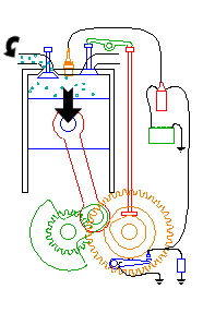
2 Stroke Engine

Two Stroke Engine

 
Speed 10 fps
The two stroke engine employs both the crankcase and the cylinder to achieve all the elements of the Otto cycle in only two strokes of the piston.
Two stroke, intake

Intake

The fuel/air mixture is first drawn into the crankcase by the vacuum that is created during the upward stroke of the piston. The illustrated engine features a poppet intake valve; however, many engines use a rotary value incorporated into the crankshaft.
Two stroke, crankcase compression

Crankcase compression

During the downward stroke, the poppet valve is forced closed by the increased crankcase pressure. The fuel mixture is then compressed in the crankcase during the remainder of the stroke.
Two stroke, transfer/exhaust

Transfer/Exhaust

Toward the end of the stroke, the piston exposes the intake port, allowing the compressed fuel/air mixture in the crankcase to escape around the piston into the main cylinder. This expels the exhaust gasses out the exhaust port, usually located on the opposite side of the cylinder. Unfortunately, some of the fresh fuel mixture is usually expelled as well.
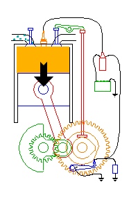
Two stroke, compression

Compression

The piston then rises, driven by flywheel momentum, and compresses the fuel mixture. (At the same time, another intake stroke is happening beneath the piston).
Two stroke, power

Power

At the top of the stroke, the spark plug ignites the fuel mixture. The burning fuel expands, driving the piston downward, to complete the cycle. (At the same time, another crankcase compression stroke is happening beneath the piston.)

Since the two stroke engine fires on every revolution of the crankshaft, a two stroke engine is usually more powerful than a four stroke engine of equivalent size. This, coupled with their lighter, simpler construction, makes the two stroke engine popular in chainsaws, line trimmers, outboard motors, snowmobiles, jet-skis, light motorcycles, and model airplanes.
Unfortunately, most two stroke engines are inefficient and are terrible polluters due to the amount of unspent fuel that escapes through the exhaust port.

4 Stroke Engine

Four Stroke Engine

The four stroke engine was first demonstrated by Nikolaus Otto in 18761, hence it is also known as the Otto cycle. The technically correct term is actually four stroke cycle. The four stroke engine is probably the most common engine type nowadays. It powers almost all cars and trucks.
 
The four strokes of the cycle are intake, compression, power, and exhaust. Each corresponds to one full stroke of the piston; therefore, the complete cycle requires two revolutions of the crankshaft to complete.
Otto intake stroke

Intake

During the intake stroke, the piston moves downward, drawing a fresh charge of vaporized fuel/air mixture. The illustrated engine features a poppet intake valve which is drawn open by the vacuum produced by the intake stroke. Some early engines worked this way; however, most modern engines incorporate an extra cam/lifter arrangement as seen on the exhaust valve. The exhaust valve is held shut by a spring (not illustrated here).
Otto compression stroke

Compression

As the piston rises, the poppet valve is forced shut by the increased cylinder pressure. Flywheel momentum drives the piston upward, compressing the fuel/air mixture.
Otto power stroke

Power

At the top of the compression stroke, the spark plug fires, igniting the compressed fuel. As the fuel burns it expands, driving the piston downward.
Otto exhaust stroke

Exhaust

At the bottom of the power stroke, the exhaust valve is opened by the cam/lifter mechanism. The upward stroke of the piston drives the exhausted fuel out of the cylinder.

Ignition System

This animation also illustrates a simple ignition system using breaker points, coil, condenser, and battery.
A number of visitors have written to point out a problem with the breaker points in my illustration. In this style ignition circuit, the spark plug will fire just as the breaker points open. The illustration appears to have this backwards.
In fact, the illustration is correct; it just moves so fast it’s difficult to see! Here’s a close-up of the frames just at the point the plug fires:
breaker point closeup
My original intent was to accurately show that the points need to remain closed for only a fraction of a second, called the dwell. By illustrating this, I inadvertently obscured the overall operation of the circuit. Perhaps someday I’ll prepare a more detailed illustration of the ignition system alone.
Larger four stroke engines usually include more than one cylinder, have various arrangements for the camshaft (dual, overhead, etc.), sometimes feature fuel injection, turbochargers, multiple valves, etc. None of these enhancements changes the basic operation of the engine.

Senin, 17 Desember 2012

Menyetel Katup Buluh 2tak


Sistem Reed Valve pada motor 2 Tak

Sistem Reed Valve Sepeda motor dengan sistem reed valve adalah sepeda motor yang pembukaan dan penutupan saluran pemasukan gas barunya diatur oleh suatu alat yang disebut reed valve atau disebut juga klep harmonika. Reed valve sangat peka terhadap pengaruh luar. Reed vave atau ...

Pengangkat Katup

Pengangkat katup Pengangkat katup adalah komponen katup yang berbentuk tabung pada mesin OHV, pengangkat katup dihubungkan dengan nok yang berhubungan dengan katup melalui batang pendorong, lebih jelasnya lihat gambar. Saat sumbu nok berputar maka pengangkat katup bergerak turun naik sehingga katup bisa membuka dan menutup. Pada mekanisme tipe konvensional masih diperlukan ...

Cara Kerja Thermostat

Cara Kerja Thermostat Temperatur cairan pendingin sangat berpengaruh terhadap performa mesin. Pada umumnya temperature kerja atau temperature dimana mesin bisa bekerja optimal berkisar antara 80-90°C. Temperatur tidak boleh terlalu lama berada diluar dari angka tersebut, thermostat adalah semacam katub yang dirancang khusus agar bisa membuka dan menutup secara otomatis sesuai perubahan temperature, ...

Cara Kerja Motor Diesel 4 Tak

Cara Kerja Motor Diesel 4 Tak Pembakaran pada motor diesel terjadi karena bahan bakar yang diinjeksikan ke dalam selinder terbakar dengan sendirinya akibat tingginya suhu udara kompresi dalam ruang bakar. Prinsip kerja motor diesel dapat dipahami dengan mempelajari urutan langkah kerja dalam menghasilkan satu usaha ...

Batang Penekan (Push Rod)

Batang Penekan (Push Rod) Batang penekan (push rod) berbentuk batang yang kecil masing-masing dihubungkan pada pengangkat katup (valve lifter) dan rocker arm pada mesin OHV. Batang katup ini meneruskan gerakan dari pengangkat katup ke rocker arm. Rocker Arm & Shaft Rocker arm dipasang pada rocker arm shaft, bila rocker arm ditekan keatas oleh batang ...

Cara Kerja Karburator Double Barrel

Cara Kerja Karburator Double Barrel Berikut ini, kita lihat cara kerja karburator double barrel yang biasa digunakan pada mobil TOYOTA. Untuk memenuhi kebutuhan kerjanya, pada karburator terdapat beberapa system, yaitu : System Pelampung System Stationary dan Kecepatan lambat ...

Durasi Kem Bhalap


durasi kem standar sangat kecil menurut saya untuk mesin balap karena kurang dari 285 derajat. Nah bagaimana kita dapat menseting agar hasilnya lebih dari 300 derajat?. Mari kita gunakan cara ukur untuk menghasilkan durasi kem yang Cara mengukur durasi kem berdasarkan patokan dial gauge berputar 1 mm. Angka durasinya hanya besar dengan cara diukur berdasarkan kem pertama menyentuh rocker arm.
Untuk mengukurnya kita pasang busur derajad yang digunakan untuk mengukur durasi di magnet sekaligus kita pasang jarum penunjuk. Untuk penunjuk ini kita bisa gunakan kawat besi yang dililitkan pada baut penutup magnet dan sisakan beberapa centi sebagai jarum penunjuk pada busur derajat. Seting mesin dalam keadaan top atau piston pada posisi Titik Mati Atas (TMA) diikuti jarum penunjuk pada titik nol busur derajad.
Pertama,ukur klep buang mulai Ex Open (EO) atau membuka. Gunakan tangan kanan untuk memegang kunci ring dan memutar mur magnet. Putar ke kanan, sementara tangan kiri anda memegang rocker arm klep out sambil digoyang untuk memastikan klep bebas atau belum disentuh bagian kem yang benjol. Jika pelatuk dirasa mulai tidak bergerak digoyang tangan, menandakan klep buang mulai terbuka. Hentikan putaran tangan kanan dan silahkan lihat angka yang ditunjuk jarum kawat penunjuk pada busur derajad. Catat hasil pengukuran.
Kemudian mengukur klep hisap In open (IO) atau membuka. Gunakan tangan kanan anda untuk memegang rocker arm klep isap. Cek dengan cara menggoyang untuk memastikan klep in masih tidak bergerak. Terus kita lakukan pemutaran mur magnet dengan kunci ring hingga rocker arm free atau bebas. Catat kembali hasil pengukuran.
Selanjutnya mengukur Ex Close (EC) atau klep buang menutup. Lakukan seperti mengukur Ex open (EO) dengan tangan kanan memastikan pelatuk masih menekan klep dengan keras. kemudian putar mesin kembali dan catatlah hasil pengukurannya.
Yang terakhir ukur In Close (IC) atau klep buang menutup. Sama seperti cara-cara sebelumnya. Jika setelah mesin diputar dan anda rasakan pelatuk mulai bergoyang, itu artinya klep mulai menutup. Kemudian catat hasil pengukuran tersebut dan kita dapat mengukur durasinya dengan rumus seperti ini :
Klep Buang = EO + EC + 180
klep Isap = IO + IC + 180
Kemudian hitung dan lihatlah angka durasi yang dihasilkan oleh motor anda......

Sumber: http://id.shvoong.com/society-and-news/1991309-durasi-kem-balap/#ixzz2FJKxWNFV

Kamis, 13 Desember 2012

Menghitung Perbandingan Klep

Hitung Bore Up dan Diameter Klep
Mungkin masih banyak  yang belum tau soal rumus-rumus dalam meng-up grade performa mesin skutik yang rata-rata jenis 4-Tak. Misal rumus menghitung volume silinder ketika melakukan bore-up dan sebagainya.

Padahal dari penggantian diameter piston tersebut, ada lagi rumus buat ngoprek komponen mesin lainnya bila ingin performanya lebih ajip.

Oke, kita mulai cara menghitung volume silinder. Masih ingat gak pelajaran matematikan di sekolah mengenai cara menghitung volume sebuah tabung silindris? Nah, sama deh dengan rumus menghitung kapasitas mesin 4-Tak.

Yakni V (dalam cm³ atau cc) = (1/4 x ? x D² x T) : 1.000. Di mana V adalah volume silinder, ? : bilangan konstanta yang nilainya 3,14, D : diameter piston dan T : langkah piston (stroke). Nah, dengan rumus ini, sobat sekalian bisa menentukan pembesaran kapasitas yang dikehendaki.

Misal di Yamaha Mio. Skutik ini mengusung diameter piston standar 50,0 mm. Sementara stroke-nya 57,9 mm. Berarti bila dimasukkan dalam rumus tadi, D = 50 mm dan T = 57,9 mm. V = 1/4 x 3,14 x (0,5)² x 0,579, hasilnya V = 113,6 cc. Itu kapasitas murninya, dibulatkan jadi 115 cc.

Trus, misal kita ingin dongkrak kapasitas silindernya jadi 150 cc atau yang mendekati, mesti pakai piston diameter berapa? Yuk, kita kalkulasi lagi. Tinggal mainkan saja angka untuk D.

Coba deh kalo kita pakai piston berdiamter 57 mm. Jika dimasukkan dalam rumus menghitung volume silinder mesin 4-Tak tadi, maka hasilnya akan didapat V = 147,67 cc. Mendekati 150 cc kan? Sementara kalau pakai piston 58 mm, hasilnya V = 152,9 cc. 

Nah, menurut Andhika Bintang Budaya atau yang di kancah balap motor nasional sering dipanggil Om Gandoz, diamater piston bisa lo dipakai untuk menentukan diameter klep yang ideal. Misal setelah mesin di-bore up, klepnya mau ikut digedein biar dapat efisiensi volumetrik yang optimal.

“Banyak yang suka salah kaprah dalam mengaplikasi klep gede. Sebab kalau diameter klep yang digunakan terlalu lebar, akan mengakibatkan velocity-nya (kecepatan aliran campuran bahan bakar) jadi terlalu rendah. Efeknya asupan gas jadi kurang maksimal,” terang salah satu tunner road race papan atas ini.

Lantas bagaimana rumus menentukan diameter klep yang ideal? Kata Om Gandoz, untuk diameter klep in adalah maksimal 50% dari diameter piston yang digunakan. Misal kalau pakai piston 58 mm, 58 x 50/100 = 29. Artinya maksimal pakai klep berdiameter 29 mm. “Itu batas maksimalnya, boleh-boleh saja pakai di bawah itu. Misal 28 mm,” tambahnya.

Sementara untuk klep out, patokan maksimumnya sekitar 85% dari diameter klep in. Ambil contoh kalau diameter klep in-nya pakai 28 mm, maka klep out-nya = 28 mm x 85 / 100 = 23,8 mm. Tapi karena untuk mendapatkan klep ukuran 23,8 mm itu susah, kata Om Gandoz pilih saja mendekati, misal pakai 23 mm.

“Jangan ambil yang lebih gede trus dibubut. Karena kalau klep sudah dibubut, kekuatannya akan berkurang lantaran lapisan hardener-nya terkikis. Efeknya, klep bakal mudah bengkok atau cepat menghantarkan panas ke seating klep yang menyebakan pemuaian tinggi,” wantinya.

Sampai di sini dah mengerti? semoga bermanfaat...

Cara Setting Noken AS


Dialing Camshaft
Banyak orang berpikir noken as adalah jantung dari sebuah mesin. Well… tidak salah memang mengingat noken AS adalah komponen pengatur katub-katub di dalam mesin untuk melakukan yoga.

Sedap memang, kalau porting intake dan exhaust mampu mengalirkan kabut udara serta gas sisa pembakaran dengan baik, mantap memang jika karburator mampu mengabutkan udara/bahan-bakar dengan jos serta exhaust system mampu melepaskan CO dengan losss…
Noken as akan bekerja sakti bila membuka pada waktunya serta bekerja menurut durasi tertentu dan berakhir on time. Oleh karenanya tidak akan berguna kita membuat noken as ekstreme untuk motor standard, juga kurang pas jika noken as dibuat agar mesin bertenaga di rpm tinggi namun dipakai untuk motocross. Terlebih penting lagi adalah pemasangan cam serta dialing sebuah noken as sehingga mereka mau membuka – menutup sesuai kehendak kita, setelan klep berapa yang pas, berapa Lobe Separation Angle yang diinginkan, berapa derajat overlapping yang dimau, dimana posisi Lobe Center diposisikan, serta maximum valve lift di mesin bukan hanya lobe lift.
Kemampuan kita mengolah data inilah yang akan menjadi sistem informasi kita dalam menentukan riset mesin balap, dimana efek jika setelan dirubah, di RPM berapa dia bekerja bagus, pada RPM mana dia lemah, saat-saat kita bercanda ria dengan mesin kemudian pembalap mencoba motor pada track untuk memberikan feedback bagi engineer akan menjadikan kita sebuah pemerintahan yang baik lho…?! Lha kan iya, bukankah kita hidup di negara Rebalap, dari pembalap oleh pembalap dan untuk pembalap… Huahahhahaha mulai ngaco..!!! Dang!
Setidaknya apa yang ingin saya bagikan di sini adalah perhitungan sederhana, bagaimana mengetahui durasi camshaft, pada bahasa internasional tentang camshaft durasi diukur saat bukaan klep atau angka dial gauge menunjuk pada 0.050 inch alias 1,27mm . Lha emangnya kita living in the jet plane.. eh emangnya kita hidup di Eropa, Amerika, Australia? Ya gak masalah ding, siapa tahu kita bisa konsultasi dengan mekanik asal Swedia seperti om saya itu huahahauahuahauahua ngaco lagi…
Well.. let us make our own standard, biasanya ngomongin durasi ya pada angkatan 1mm, jadi saat kamu diliput tabloid, dan bicara durasi motor kamu bilang Cuma 260 derajat bos… itu diukur pada angkatan 1mm, jadi kan orang pada gak tahu durasi sebenernya saat klep mulai membuka 0,15mm dan hampir menutup 0,15mm, misalnya… hehhehehe senengane kok main rahasia. Biasa… kalau sudah terkenal jangan lupa sombong. Hakhakahkahak… But it’s not me. Secara saya belum terkenal.
Supaya lebih gampang kita akan berbagi contoh menghitung durasi noken as Yamaha Vega r
Intake membuka 27 derajat sebelum TMA, menutup 53 derajat setelah TMB
Exhaust membuka 55 sebelum TMB, menutup 29 derajat setelah TMA
Mari kita hitung durasi, LC, LSA
durasi In = 27 + 180 + 53 = 260 derajat
durasi Ex = 55 + 180 + 29 = 264 derajat
Lobe center In = 260 / 2 – 27 = 103 derajat
Lobe center Ex = 264 / 2 – 29 = 103 derajat
LSA = 103 derajat
Dari LSA kalian akan tahu karakter sebuah camshaft, dari posisi LC kalian akan bisa menentukan maximum lift apakah sudah tepat atau tidak, dari durasi kalian akan tahu pada RPM berapa dia akan bekerja baik.
salam gas polllllll.

Rahasia Mekanik ULO Bhalaaph

MEMBUKA RAHASIA MEKANIK BALAP


KOREK MESIN MOTOR
Korek mesin motor kami buat untuk para bikers dan penggila kecepatan roda dua. Sayangnya performa motor baru dari semua pabrikan di rasa kurang untuk menaklukan medan aspal buat kita para penakluk kecepatan,ini dikarenakan untuk ketahanan mesin sepeda motor pabrikan agar usia motor jadi lebih panjang, minimal memenuhi target garansi mesin 3-5 tahun.
            Buat kita kecepatan motor pabrikkan dirasa sangat kurang,itu tidak dapat memenuhi hasrat kita yang haus akan kecepatan motor secara maximum, hasrat kita untuk menaklukan kecepatan yang berbanding terbalik dengan waktu,,,jarak sejauh-jauhnya dengan wakru yang sesingkat-singkatnya. Membuat motor lari sekencang-kencangnya adalah harapan dari semua pejuang di aspal, khususnya kita yang bermain di balap resmi ataupun balap jalanan (liar). Siapa yang tercepat di jalur aspal itulah juara dan raja jalanan, kita kan menghargai itu sebagai raja balap. Menjadi seseorang yang berdiri gagah diatas podium tertinggi,
Kesempatan Memang Datang Berkali-kali, Tapi Siapa Yang Tercepat Mengambil Kesempatan Itu Ialah Yang Terbaik
            Untuk memenuhi  tuntutan itu kami buat Panduan “Korek Mesin Sepeda Motor ” sebagai panduan dan referensi bagi para penggila balap motor yang ingin memaksimalkan kinerja engine/mesin, Kami berikan semua ilmu yang kami dapat dari lapngan secara lengkap. Panduan  Korek Mesin Sepeda Motor ” berisi tentang cara memodifikasi dan korek motor balap, baik harian, full, ataupun ekstrim. Kami coba pandu bagaimana memecahkan masalah-masalah yang di hadapi dalam para mekanik dalam langkah-langkah apa saja yang harus dilakukan setiap tahap dari awal sampai akhir, mulai dari penggunaan rumus-rumus, alat-alat yang digunakan, pengukuran, penyetingan, patokan-patokan semua ukuran beserta penjelasannya, serta yang tak kalah penting adalah pengalaman-pengalaman kami yang kami bagikan kepada anda beserta pengalaman para mekanik-mekanik balap yang kami rangkum dan kami praktekan, tidak ada manusia yang sempurna dan di atas langgit masih ada langit itulah yang mendorong kita sebagai manusia harus selalu berbagi ilmu,,,kita harus percaya ilmu itu tidak ada habisnya, dan akan terus bertambah walaupun itu kita bagikan terus ke orang lain.
Dapatkan Sekarang Hanya Dengan Rp 450.000,00(sudah termasuk ongkos kirim)
            “Korek Mesin Sepeda Motor” ini kami susun selain berdasarkan pengalaman kami dan juga dari beberapa mekanik balap nasional beserta sekolah-sekolah balap yang terkemuka.tidak luput juga dari peninggalan eyang buyut kita  Alexander Graham Bell dalam bukunya “four stroke performance tuning” dan “two stroke performance tuning ” yang rumus-rumusnya masih di pakai oleh semua mekanik di dunia.(TERIMA KASIH eyang)
            Panduan korek mesin ini mencakup banyak kelas di ajang balap, baik road race, Drug, dan grass track.ini sesuai dengan bidang balap yang anda geluti. karena setiap ajang tersebut mempunyai cara korek yang sangat berbeda dalam pengerjaannya.
            Dalam “Korek Mesin Sepeda Motor”berisi tentang segala aspek yang harus dilakukan untuk mencapai TOP SPEED,kita kan bahas dari satu persatu. Dibawah ini adalah sebagian yang harus dikerjakan agar performa mesin meledak kecepatannya:
1.     Head
Sudut Derajat Klep
Modifikasi Klep
Porting
Ukuran Lubang   Inlet
Ukuran Lubang Exhaust
Nokn As /Kem(Durasi dan Profil)
Per Klep
Rocker Arm
dll
2.     Blok
Piston
Stroke
dll
3.     Crankcase
Kruk As
Kopling
Gigi Rasio
Dan tidak akan lupa yang yang di bawah ini (SAKRAL)
Karburator
Ignation(pengapian)
Magnet
Knalpot (bentuk dan ukuran pipa sesuai CC)
Dan data –data tambahan yang kami tambahkan sebagai penunjang diatas
Jadilah Yang Terbaik.Tidak Ada Kata Terlambat Untuk Belajar………..Belajar Dari Kegagalan  Dan Semangat Pantang Menyerah Itulah Mental Sejati Seorang Mekanik Para Juara
Jendela balap masih terbuka lebar untuk kita yang mau berjuang di bidang ini.Tidak ada hal yang tidak mungkin bagi kita manusia di dunia ini, kita harus percaya itu. Kembangkan terus potensi anda, percayakan dengan panduan ‘Korek Mesin Sepeda Motor ’ anda bisa menjadi mekanik yang punya potensi,skill, dan siap bersaing. Kerja sama yang baik antara kita dapat menyebarkan ilmu korek mesin kepada semua orang adalah harapan kami demi kemajuan dunia balap tanah air, kebahagian terbesar bagi saya adalah ilmu kita dapat berguna bagi nusa dan bangsa.

Panduan “korek mesin motor” adalah buku yang dirangkum dalam 200 halaman berwarna,berisi rumus,aplikasi,teknik modifikasi mesin dan setting mesin balap
 
MAJU TERUS DUNIA BALAP NASIONAL

Dari harga Panduan kami gunakan untuk riset mesin balap yang nantinya akan kami update/bagikan hasil riset kami setiap harinya kepada anda di website kami, Kita semua tahu riset motor balap masih berjejer di bilangan puluhan juta rupiah. Oleh karena itu kerja sama antara kita sangat membantu untuk kepentingan ilmu kita bersama..Kunjunganilah website kami setiap waktu untuk dapatkan informasi “KOREK MESIN MOTOR” terbaru jilid selanjutnya.
Kami juga menerima pengiriman Panduan “korek mesin Motor” lewat email seharga 250 ribu
 
 .......