Rabu, 03 April 2013

Vega Zr Beda Speak dengan Vega R

Yamaha Vega-ZR
Yamaha Vega ZR yang menurut PT Yamaha Motor Kencana Indonesia (YMKI) merupakan benar-benar hasil pengembangan dari generasi Vega R dan tidak sekedar ganti baju belaka. Vega ZR merupakan jawaban atas permintaan konsumen yang menuntut perubahan secara menyeluruh baik tampilan sampai mesin yang digunakan. Apa memang signifikan perbedaan antara Vega ZR dan Vega R? mari coba kita bahas.

Performa Mesin
Walau Vega ZR memiliki jumlah CC lebih besar 3,4CC bukan jaminan ZR lebih ganas dibanding Vega R, bila digunakan untuk berboncengan ZR hanya mampu berlari hingga kecepatan 90km/jam, sedang Vega R mampu berlari hingga 100km/jam. Sedang bila dikendarai sendirian Vega ZR mampu menembus angka 110km/jam dan 120km/jam untuk Vega R.
Perpindahan gigi pada Vega ZR terasa lebih halus dan ringan karena mengadopsi sistem kopling tipe diafragma tidak seperti Vega R yang masih menggunakan model pegas, selain itu perbandingan gigi rasio Vega ZR juga lebih rapat sehingga memberikan respon tenaga yang lebih baik.
Konsumsi BBM
Dengan bahan bakar premium, Vega ZR dapat menempuh 46,26 km/liter, sedang Vega R hanya sanggup menempuh 43,90 km/liter.
Kenyamanan Berkendara
Vega ZR memiliki posisi berkendara lebih nyaman dibanding Vega R, jarak dan lebar setang, posisi duduk dan pijakan kaki Vega ZR memiliki komposisi yang pas. ZR juga didesain lebih bersahabat dengan kaum hawa yang berpostur tubuh antara 155-160 cm, karena posisi jok Vega ZR lebih rendah 5 mm dibanding Vega R, selain itu penampang jok lebih luas.
Yamaha Vega-R
Untuk kegesitan membelah kemacetan kota, Vega R lebih unggul dibanding Vega ZR, hal ini mungkin karena bobot Vega R lebih ringan 1,9kg dibanding Vega ZR, selain itu ukuran wheelbase Vega R menggunakan ukuran 1195 mm, sedang Vega ZR menggunakan ukuran 1235 mm. Tetapi bila digunakan untuk jalur luar kota, Vega ZR lah juaranya, karena Vega ZR lebih mantap dan stabil meski dikebut hingga top speed. Tipe sokbreker belakang Vega ZR menggunakan tipe baru yang memiliki diameter as lebih besar 2 mm dibanding Vega R, disamping berukuran lebih besar diameternya sok itu juga lebih pendek sehingga mengurangi efek ayun, akibatnya peredaman Vega ZR terasa sedikit kaku daripada Vega R.
Kesimpulan
Kelemahan Vega ZR hanya di performa mesin, selebihnya bisa dikatakan Vega ZR lebih unggul dibanding Vega R. Mulai dari sisi stabilitas, posisi berkendara hingga konsumsi bahan bakar. Kedepan YMKI berencana mengembangkan performa mesin ZR karena melihat spesifikasinya memang mesin ini masih punya banyak peluang untuk dikembangkan.
Perbandingan Singkat
Vega R
- Kapasitas mesin : 110,3 cc
- Daya maksimum : 6,6 kw/8.000 rpm
- Torsi maksimum : 9,0 Nm/5.000 rpm
- Diameter x langkah : 51×54 mm
- Panjang x lebar x tinggi : 1890 x 675 x 1030 mm
- Jarak sumbu roda : 1195 mm
- Jarak terendah : 146 mm
- Berat : 95,1 kg
- Kunci jok : body samping
- Lampu sein : pada batok
- Indikator gigi persneling : ada
- Behel : pipa kotak
- Dudukan footstep belakang : dari cor
- Air induction system : di samping mesin
- Harga : Rp.11.500.000 ( OTR Jakarta)
Vega-ZR
- Kapasitas mesin : 113,7 cc
- Daya maksimum : 6,0 kw/7.500 rpm
- Torsi maksimum : 8,3 Nm/4.500 rpm
- Diameter x langkah : 50×57,9 mm
- Panjang x lebar x tinggi : 1930 x 660 x 1055 mm
- Jarak sumbu roda : 1235 mm
- Jarak terendah : 126 mm
- Berat : 97 kg
- Kunci jok : body belakang
- Lampu sein : pada dek
- Indikator gigi persneling : hanya netral dan top
- Behel : pipa silindris
- Dudukan footstep belakang : dari pipa bulat
- Air induction system : di atas mesin
- Harga Rp. 11.800.000 (OTR Jakarta)
foto dari yamaha-motor.co.id

Kamis, 07 Maret 2013

Korek Harian Vega

untuk harian special kita buat seringan mungkin dengan rumus dan perhitungan tentunya tapi tetap mengedepankan hasil di tenaga puncak yang keluar, memaksa mesin harus tetap teriak, dengan hasil rpm bisa sampai puncak rpm tertinggi tentunya.Part/Komponen yang kita coba bahas menggunakan sparepart subtitusi(pengganti)dari pabrikan lain yang bukan ricing,menghemat harga karena buat harian para bikers.Kita bisa pake klep shogun, dengan panjang batang klep 67 milimeter, kita buat muncul klep nya 29 milimeter dari pangkal head, gap dibuat 4.5 milimeter.Gap lebar layaknya pacuan motor road race, berguna untuk mendapat area overlaping yang tinggi , sehingga tenaga di putaran atas membaik. Disokong oleh aplikasi untuk pir klep milik CS-1 agar tidak terlambat mengembalikan klep exhaust di putaran 10.000 RPM.Nokn As/Kem dipatok   lobe lifter cam 7 milimeter, dan dengan papas Nokn As 1.5 milimeter . Area intake port kita papas 5 milimeter, porting dibuat kotak yang hampir sesuai desain suzuki satria Fu150. Terpenting kita tahu prinsipnya, yang diinginginkan adalah aliran udara berkelok kesamping, bergumpal di area dekat bushing klep, lalu ditekan membentuk badai homogenus masuk ke silinder saat katub terbuka. Efisiensi ruang bakar yang mampu mencegah detonasi adalah campuran udara/bahan-bakar yang berputar dan termixing dalam silinder. Oleh karenanya kita berani mematok perbandingan volume yang disapu dengan volume yang ditinggalkan hingga 11.5 : 1.Tak lupa teknik modifikasi terbaru kita terapkan, valve back cut , ini kuncian yang menambah efisiensi area porting menjadi sebesar 30%, area kiri – kanan bushing klep kita lebarkan 110 % dari diameter klep intake. Hasilnya, Nafas terus gak habis-habis motornya, puncak kecepatan 120 KPJ di gigi 3 kemudian pindah ke persneling final masih mampu naik percepatannya. Padahal jantung dapur pacu mesin Yamaha Vega ini hanya kita rubah memakai piston kawasaki kaze oversized 1 milimeter, piston ini masih menjadi andalan dari jaman dulu, hanya sekarang tinggal bagaimana pintar kita mensiasatinya. Disinilah skill sedikit dibutuhkan karena blok vega lebih rendah 2 milimeter dibanding Jupiter Z atau Vega R new , inilah kesempatan membentuk dome pistonnya layaknya piston FIM – izumi. Piston yang muncul dari blok di beri tanda garis dengan pisau, piston direndahkan hingga 0.5 milimeter dibawah garis itu, dan dome yang terbentuk dilesakkan ke dalam ruang bakar. Tak lupa speeling kedalaman coakan klep pada piston diberi lebih dalam kurang lebih 1 mm dari posisi overlaping klep. Kalau menurut Tom Monroe, dalam bukunya Engine Builder Handbook, sebaiknya kedalaman coakan klep exhaust pada piston diperdalam, karena kecenderungan klep buang dalam posisi turun hanya mengandalkan kekuatan pir klep untuk mengembalikan posisinya, jika terlambat maka fatal akibatnya – merusak head-klep-piston-liner. Itulah kenapa seringkali klep buang yang mengalami kebengkokan atau bahkan patah.

Blok yang pendek, piston bisa dibuat nge-dum, dengan jantung sebesar itu, potensial  kubah ruang bakar masih bisa dipacu dengan klep milik Honda sonic dengan dimensi 28 / 24. Apabila dengan katub 26 / 22 , seperti motor pembalap pemula tetep masih bisa galak. Spuyer  milik jupiter z, pilot jet # 25, main jet # 110. Tanpa reamer, intake manifold standard. Box filter harus terpasang supaya debu tidak tersedot waktu motor dibawa ke Top Speed. Ubahan lain di sektor kampas kopling, kita mengandalkan kampas kopling racing dari Indopart, pir kopling dari motor yamaha RX-KING, balancer 900 gram. Magnit standard, cdi 4st, coil standard. Tidak ada yang istimewa dari setiap part/komponen, yang terpenting tercapai konsep harian dan butuhnya hanya transfer tenaga yang besar. Lebih bagus langsung ubah gigi rasio , diatur pada   sekunder nomor 3 dipakai mata berjumlah 30. Membuat reduksi dari gigi 2 ke 3 lebih rapat dan cepat, dan masih menyisakan nafas pada gigi 4. Hasil top speed jarum speedometer mentok cukup tinggi, dengan patokan final gir depan 15 -35 untuk 400meter.Muffler untuk mengejar putaran atas, silinser mengerucut kecil, pipa 25 milimeter pada leher, disambung 27 milimeter di step ke – 2, silinser 15 milimeter adalah lubang kasa, dengan jumlah lubang pada pipa 16 buah dengan diameter 6 milimeter.

Kita order pemakaian katub shogun, dengan panjang batang klep 67 milimeter, kita buat muncul klep nya 29 milimeter dari pangkal head, gap dibuat 4.5 milimeter .
Porting kotak - kotak - kotak , :D
Gap lebar layaknya pacuan motor road race, berguna untuk mendapat area overlaping yang tinggi , sehingga tenaga di putaran atas membaik. Disokong oleh aplikasi untuk pir katub milik CS-1 agar tidak terlambat mengembalikan klep exhaust di putaran 10.000 RPM. Sayangnya kok telat nemuinnya, malah pakai pir katub shogun sempat patah pir katub nya kena lobe lifter cam 7 milimeter, hasil dari pemangkasan noken as 1.5 milimeter. Untung ga patah klep nya, fffiiuuhhh… Kalau penari dangdut goyang patah-patah mah, aaajjjiiibbb :D
Kalau ini head jupiter buat Bore Up 200 cc milik guruku :Dcak Bayu "Tape" Hi Speed Performance
Area intake port kita papas 5 milimeter, porting dibuat kotak – maunya meniru desain suzuki satria Fu150, hehehe… kebanyakan garap mesin FU jadi keblinger gini ^_^  eh, ternyata enak banget kok :DSekali-kali gak ngikutin.Terpenting kita tahu prinsipnya, yang diinginginkan adalah aliran udara berkelok kesamping, bergumpal di area dekat bushing klep, lalu dihajar membentuk badai homogenus masuk ke silinder saat katub terbuka, asimetrical porting akan membantu membentuk swirl, dan dari buku teori dasar mesin torak, efisiensi ruang bakar yang mampu mencegah detonasi adalah campuran udara/bahan-bakar yang berputar ter-aduk2 dalam silinder. Oleh karenanya kita berani mematok perbandingan volume yang disapu dengan volume yang ditinggalkan hingga 11.5 : 1.
Tak lupa teknik modifikasi terbaru kita terapkan, valve back cut, ini kuncian yang menambah efisiensi area porting menjadi sebesar 30%, area kiri – kanan bushing klep kita lebarkan 110 % dari diameter klep intake. Hasilnya, Nafaaaaassss terus gak habis-habis motornya, puncak kecepatan 120 KPJ di gigi 3 kemudian pindah ke persneling final, jupitr MX lewaaaaaaaaattt !!
jantung dapur pacu mesin Yamaha Vega kita rubah memakai piston kawasaki kaze oversized 1 milimeter, piston ini masih menjadi andalan dari jaman dulu, hanya sekarang tinggal bagaimana pintar kita mensiasatinya. Disini serunya, karena blok vega lebih rendah 2 milimeter dibanding Jupiter Z atau Vega R new , inilah kesempatan membentuk dome pistonnya layaknya piston FIM – izumi. Piston yang muncul dari blok di beri tanda garis dengan pisau, piston direndahkan hingga 0.5 milimeter dibawah garis itu, dan dome yang terbentuk dilesakkan ke dalam ruang bakar. Tak lupa speeling kedalaman coakan klep pada piston diberi lebih dalam + – 1 milimeter dari posisi overlaping klep. Kalau menurut Tom Monroe, dalam bukunya Engine Builder Handbook, sebaiknya kedalaman coakan klep exhaust pada piston diperdalam, karena kecenderungan klep buang dalam posisi turun hanya mengandalkan kekuatan pir klep untuk mengembalikan posisinya, jika terlambat maka fatal akibatnya – merusak head-klep-piston-liner. Sudah sadar kan, kenapa seringkali klep buang yang mengalami bengkok atau patah?
Blok pendek, piston bisa dibuat nge-dum :D
Dengan jantung sebesar itu, potensial  kubah ruang bakar masih bisa dipacu dengan katub milik Honda sonic dengan dimensi 28 / 24, tapi toh ini untuk riset siapa tahu dapet pesenan juga untuk bikin mesin MP 3, kan dengan katub 26 / 22 , anggap aja motor pembalap pemula tapi tetep kudu bisa galak :)Supplay bahan-bakar masih mengandalkan milik jupiter z, pilot jet # 25, main jet # 110. Tanpa reamer, intake manifold standard. Box filter terpasang supaya debu tidak tersedot waktu motor dibawa ngebut nyalip bus, atau truk. Gasss terus pokoknya.
Ubahan lain di sektor kampas kopling, kita mengandalkan kampas kopling racing dari Indopart, pir kopling dari motor jambret, yamaha RX-KING, balancer 900 gram. Magnit standard, cdi 4st, coil standard. Tidak ada yang istimewa memang, toh butuhnya hanya transfer tenaga. Lebih dahsyat langsung ubah gigi rasio , ditata pada sekunder nomor 3 dipakai mata berjumlah 30. Membuat reduksi dari gigi 2 ke 3 lebih rapat dan cepat, dan masih menyisakan nafas pada gigi 4. Hasil top speed jarum speedometer mentok cukup lumayan lah, digapai dengan mudah melalui final gir depan 15 – belakang 35.
, untuk mengejar putaran atas, silinser mengerucut kecil, pipa 25 milimeter pada leher, disambung 27 milimeter di step ke – 2, silinser 15 milimeter adalah lubang kasa, dengan jumlah lubang pada pipa 16 buah dengan diameter 6 milimeter.

Rabu, 09 Januari 2013

Bearing Racing


Space Age Ceramic Bearings Make Steel Bearings Obsolete for Racing!

Are you running "parts store" grade steel bearings in your race car? Then you're racing with the lowest cost bearing available and not making use of the latest technology in bearings. Ceramic Bearings offer many benefits for the racer, and the cost to upgrade isn't that bad!
  • Faster ET's and Lap Times - Ceramic bearings have 1/10th the friction of steel which means faster ET's and lap times! Can you push your car with one hand?

  • 60% Lighter Weight - Silicon Nitrate balls weigh 60% less than steel balls of the same size. Reduce your bearing rotating weight!

  • Longer Life - Ceramic Bearings last up to 5 times longer than steel!

  • Cooler Running - Ceramic Bearings have no micro weld adhesion between the balls & races which means lower friction. Ceramic also has a lower amount of thermal expansion which also reduces temperatures. Bearings run cooler and vibration levels are lower at high RPM

  • No Special Handling or Cleaning - If they get sluggish rinse with paint thinner, put a drop of oil in and go racing!

  • Before You Buy - Understand that there are different grades of Silicon Nitrate Ceramic balls available on the market. Differences include impact resistance, roundness, surface finish and wear resistance. The highest quality bearings are Grade 5 (the very best), then you have grades 25, 50 and 100 which are more suitable for less demanding applications. Performance Bearing uses ONLY Grade 5 in our products, the highest quality and lowest drag bearings available for racing.
Performance Bearing offers replacement Ceramic Bearings to replace your antique steel bearings in your Wheel and Axle Bearings, Transmission and Gearbox Bearings, Camshaft Bearings and special applications for High Speed Industrial Machine Tools.
Since 1999 we've specialized in Free Spinning Ceramic Racing Bearings in both the full complement style (no retainer) and the crown retainer style. We also make our own retainers in house on a State of the Art CNC machine, we do not use a stamped or molded retainer like most of the competition. When you buy from Performance Bearing, you're getting the highest quality Ceramic Bearings available!
Ceramic Bearings work great for High Speed Industrial Equipment, Race Cars, Racing Bicyles, Motorcycles, ATV's, Snowmobiles and Go Carts... any place you want to reduce friction!
 

Rabu, 19 Desember 2012

2Tak Engine

A Running Two Stroke Engine:

A two-stroke in its purest form is extremely simple in construction and operation, as it only has three primary moving parts (the piston, connecting rod, and crankshaft). However, the two-stroke cycle can be difficult for some to visualize at first because certain phases of the cycle occur simultaneously, causing it to be hard to tell when one part of the cycle ends and another begins.
Several different varieties of two-strokes have been developed over the years, and each type has its own set of advantages and disadvantages. The subject of the animated GIF (and this dissertation) is known as a case-reed type because induction is controlled by a reed valve mounted in the side of the crankcase.
The easiest way to visualize two-stroke operation is to follow the flow of gases through the engine starting at the air inlet. In this case, the cycle would begin at approximately mid-stroke when the piston is rising, and has covered the transfer port openings:
Transfers closed
As the piston moves upward, a vacuum is created beneath the piston in the enclosed volume of the crankcase. Air flows through the reed valve and carburetor to fill the vacuum created in the crankcase. For the purposes of discussion, the intake phase is completed when the piston reaches the top of the stroke (in reality, mixture continues to flow into the crankcase even when the piston is on its way back down due to the inertia of the fuel mixture, especially at high RPM):
Top-Dead-Center
During the down stroke, the falling piston creates a positive pressure in the crankcase which causes the reed valve to close. The mixture in the crankcase is compressed until the piston uncovers the transfer port openings, at which point the mixture flows up into the cylinder. The engine depicted here is known as a loop-scavenged two-stroke because the incoming mixture describes a circular path as shown in the picture below. What is not readily apparent in the picture is that the primary portion of the mixture is directed toward the cylinder wall opposite the exhaust port (this reduces the amount of mixture that escapes out the open exhaust port, also known as short-circuiting):
Mixture Transfer
Mixture transfer continues until the piston once again rises high enough to shut off the transfer ports (which is where we started this discussion). Let's fast-forward about 25 degrees of crank rotation to the point where the exhaust port is covered by the piston. The trapped mixture is now compressed by the upward moving piston (at the same time that a new charge is being drawn into the crankcase down below):
Compression
Somewhat before the piston reaches the top of the stroke (approximately 30 degrees of crank rotation before top-dead-center), the sparkplug ignites the mixture. This event is timed such that the burning mixture reaches peak pressure slightly after top dead center. The expanding mixture drives the piston downward until it begins to uncover the exhaust port. The majority of the pressure in the cylinder is released within a few degrees of crank rotation after the port begins to open:
Exhaust
Residual exhaust gases are pushed out the exhaust port by the new mixture entering the cylinder from the transfer ports.
That completes the chain of events for the basic two-stroke cycle. The discussion is not complete. The animated demonstration has an added device commonly known as an expansion chamber attached to the exhaust port. The expansion chamber (an improperly named device) utilizes sonic energy contained in the initial sharp pulse of exhaust gas exiting the cylinder to supercharge the cylinder with fresh mixture. This device is also known as a tuned exhaust.
Picking up the discussion at the point shown by the exhaust blowdown picture above, an extremely high energy pulse of exhaust gas enters the header pipe when the piston begins to open the exhaust port:
Initial Pressure Pulse
The sonic compression wave resulting from this abrupt release of cylinder pressure travels down the exhaust pipe until it reaches the beginning of the divergent cone, or diffuser, of the expansion chamber. From the perspective of the sound waves reaching this junction, the diffuser appears almost like an open-ended tube in that part of the energy of the pulse is reflected back up the pipe, except with an inverted sign (a rarefaction, or vacuum pulse is returned). The angle of the walls of the cone determine the magnitude of the returned negative pressure, and the length of the cone defines the duration of the returning waves:
Returned Negative Pressure
The negative pressure assists the mixture coming up through the transfer ports, and actually draws some of the mixture out into the exhaust header. Meanwhile, the original pressure pulse is still making its way down the expansion chamber, although a considerable portion of its energy was given up in creating the negative pressure waves. The convergent section of the chamber appears like a closed-end tube to the pressure pulse, and as such causes another series of waves to be reflected back up the pipe, except these waves are the same sign as the original (a compression, or pressure wave is returned). Notice that this cone has a sharper angle than the diffuser, so that a larger proportion of energy is extracted from the already weak pressure pulse:
Mixture Extraction
This pulse is timed to reach the exhaust port after the transfer ports close, but before the exhaust port closes. The returning compression wave pushes the mixture drawn into the header by the negative pressure wave back into the cylinder, thus supercharging (a bigger charge than normal) the engine. The straight section of pipe between the two cones exists to ensure that the positive waves reaches the exhaust port at the correct time:
Supercharging
Since this device uses sonic energy to achieve supercharging, it is regulated by the speed of sound in the hot exhaust gas, the dimensions of the different sections of the exhaust system, and the port durations of the engine. Because of this, it is only effective for a very narrow RPM range. This explains why two-stroke motorcycles equipped with expansion chambers have such vicious powerbands (especially in the old days before variable exhaust port timing existed). With the design illustrated here (i.e. a single divergent stage and a single convergent stage), the powerband of the engine will be akin to a 'light switch' - once the expansion chamber goes into resonance, there will be a HUGE, almost instantaneous increase in power. The powerband can be softened somewhat by reducing the angles on the cones, but this is simply due to a lower degree of supercharging. In order to get the best of both worlds (a large power increase and a wide powerband), the cones should consist of several sections, with a different angle for each section. Proper design of even a simple expansion chamber is somewhat of a black art, even though formulae exist that will get you in the ballpark (there is quite a bit more to this than simply choosing the appropriate angles and lengths based on sonic velocity - everything about the pipe comes into play, including the headpipe diameter and length, and the tailpipe ('stinger') diameter and length). Design of a multi-stage expansion chamber becomes incredibly difficult - it basically comes down to the old 'cut and try' approach in the end. This of course is not even considering whether or not the exhaust and transfer port timings and outlet areas have been optimized for expansion chamber use.


And last but not least a running 2 stroke engine animation:

Two-stroke animation failed to load try www.dukesofwindsoar.com/page_photos/2stroke/two-stroke_c.gif

Selasa, 18 Desember 2012

Kopling Bebek 4Tak

Setel / Setting Kampas Kopling bebek 4 tak

ni agan agan yang punya masalah di transmisi seputar kopling buat motor dengan transmisi otomatis, biasanya kopling selip, ati gigi presneling susah  mundur, biasanya kebanyakan bengkel menyarankan untuk langsung ganti kampas kopling, ya maklumlah gan biar dagangannya laku, untung tambah gede gan, tapi bagi konsumen udah kantong tipis masih ganti kopling yang indoparts saja minimal 70ribu gimana kalo yang asli bisa tidak makan satu minggu… hehehehe


kampas kopling motor bebek. type :plat basah

Nah Biar ga kejebak tuh sama bengkel2 “nakal” makanya ane kasih informasi seputar masalah tersebut, kalo ketemu masalah tersebut jangan pusing mikirin modal buat ganti kampas kopling, bisa saja cuma setelan/settingan/pengaturannya yang tidak pas.

buat cara ngesetnya putar baut pada bagian kanan blok mesin biasanya sih agak belakang dekat pengisian oli.


tu baut tumpuk 2 gan, baut kecil tengah ukur 8 itu buat setting kampas, ama murnya ukur 14 diluar buat ngancing/mengikat baut setelan biar ga muter2 lagi.

cara setetelnya:

-putar mur besar 14an kekiri hingga kendor.

-putar baut kecil (baut setelan) kearah kanan hingga mentok

-putar baut kecil kekiri sampai terasa ada sentuhan, (untuk menetralkan posisi)

-putar baut kecil kekanan antara 1/4 (seperempat)sampai 1/8(seperdelapan) putaran ini adalah inti penyetelan.


-tahan posisi baut kecil lalu kencanggkan mur besar untuk mengunci posisi baut kecil


cara test setelannya:

-standarkan ganda biar ban belakang menggantung

-putar gas 1/4 putaran sekitar mesin 1000- 2000rpm

-bila ban belakang diam (tidak berputar) berarti setelan berhasil

-bila berputar berarti setelan gagal


Nah itu gan  cara buat ngeset setelan kampas kopling, kalo disetel berulang2 gagal terus yah bawa kebengkel saja tapi siap2 puasa ya gan, berarti tu kuda besi minta diperhatiin sama agan… hehehehe Jangan Lupa Klik Iklan Disamping ini untuk donasi. Terima kasih

Ignition timing for CDI

About timing

Timing a bike refers to setting when a spark jumps the gap between the center electrode and the ground electrode on a spark plug and its relation to the rotation of the crankshaft. Adjusting when this happens is very important and can significantly affect how the bike runs.
This has been achieved by using a mechanical system called points ignition for many years. Recently, advances in electronics have introduced the CDI (Capacitor Discharge Ignition) which is what we will examine here.
Lets look at the parts of a CDI system and how they work.
  1. Flywheel (internal rotor, or external rotor) with magnets
  2. Stator plate with coils and pickup/hall sensor (as opposed to a points stator plate, which has points and a condensor)
  3. CDI box
  4. High Tension Coil
  5. Spark Plug
[edit]

Timing and CDI's

We won't go into great depths on how the CDI produces the spark, or how electricity works in general (we are only interested in getting the spark to happen at the appropriate time) but I will glance over the important parts that relate to the timing.
[edit]

The basics

The flywheel is attached to the crankshaft. When the engine is running, the flywheel spins in either a clockwise or counterclockwise direction (depending on your engine). The stator plate is attached to the engine and stays stationary while the engine is running. The stator has two main ignition components; a coil, and a hall sensor/pickup. When the flywheel spins next to the coil, the magnetic fields from the magnets produce electrical current that flows through wires wrapped around the coil. A wire attached to the stator carries this current to the CDI box which has a capacitor. The current is stored in the capacitor (a capacitor is a little like a battery) until it is ready to be sent to the spark plug to create the spark. The hall sensor detects changes in the magnetic field and sends a signal to the CDI box via a wire. This signal is created by the hall effect and it happens when the flywheel magnet changes poles over the top of the pickup (N to S, or S to N depending on the flywheel and it’s rotation). When this signal is received by the box, it discharges the capacitor and sends that electrical current to the spark plug (through the HT coil which converts the current to high voltage) and this is the point when the spark plug fires.
[edit]

Effects of timing and curves

Before we actually set the timing on a bike, lets talk about the effects of different timing, and why some CDI boxes have a curve.
Once the timing has been set somewhere around a few mm before the piston reaches top dead center the bike will run. Too far in either direction and it will run very poorly, but get it close to optimal and it will run nicely. Once it runs well, changes in spark timing have the most effect on the temperature of the gasses that exit out the exhaust port of a cylinder. What this means is that if a spark happens somewhere around 2.5mm before top dead center (BTDC), combustion will complete earlier in the cycle and have time to dissipate its heat into the head, piston, and cylinder before the exhaust port opens. This means that the gasses that exit out the exhaust will be cooler. When the spark happens later, lets say somewhere around .5mm BTDC the combustion process completes later, and the exhaust gasses have less time in contact with the head, piston, and cylinder walls. This means the gasses that exit out the exhaust port will be hotter. Why do we care what temperature the exhaust gasses exit? I’m glad you asked… the hotter the gasses, the faster the gasses will travel down the exhaust pipe. The cooler the gasses, the slower they will travel. So why do we care how fast they travel? I’m glad you asked… Slower gasses will move the powerband of a pipe to LOWER rpms. Faster gasses will shift the powerband of a pipe to HIGHER rpms. So as timing changes, so does the powerband of a pipe. We can use this information to our advantage. If we have variable timing we can have a variable powerband of a pipe, right? So why not have the powerband of a pipe be at lower rpms when the engine is actually at lower rpms and then have the powerband of a pipe be at higher rpms when the engine is actually at higher rpms. This is exactly what happens in cdi’s that have a curve. They start out with more advanced timing at lower rpms (to shift the powerband of the pipe to lower rpms), and then retard the timing at higher rpms (to shift the powerband of the pipe to higher rpms). Some cdi’s dont have a curve though, and you have to compromise. If you do not have a curve on your cdi, you set the timing so the powerband of your pipe is where you want it. Set it more advanced to lower the peak power rpm value, and set it more retarded to have the peak power of the pipe at a higher rpm value. There are limits to how far you can advance/retard your timing however, as your bike may not run properly if it is too far in either direction.
[edit]

Setting the timing

Now that we know the effects of timing values lets talk about how to set the timing on a CDI.
Special tools Needed:
  1. Timing light
  2. Micrometer
  3. Sharpie marker
  4. Piston stop


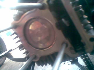
• Put a line on the flywheel anywhere with a sharpie in a fashion similar to what was done in this image (ignoring the mark on the engine for the moment; only mark the flywheel).

• Install the flywheel but tighten it only enough so that it can't spin freely, as you'll be taking it off in a minute. Hook up the timing light, and either spin the engine (spark plug removed, but grounded so it sparks) with a power drill or have a buddy pedal it, and make a mark on the engine case (or something stationary) where the line you drew shows up.
You now know that the spark will always fire when the line on the flywheel matches up to the line you drew on the case. You may want to at this point, hold the two lines together, and draw two more lines in a more convenient place, as they may wind up being on the bottom, but don't forget to erase the old lines so as not to get them confused.

• Loosen the flywheel nut and pull the flywheel off, but then put the nut back on hand tight so you can still rotate the flywheel but tight enough so that it won't wander on its own.


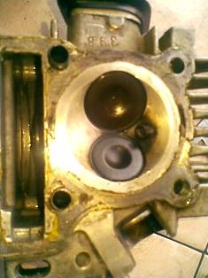
• Now, this is where the calipers become handy. Some people don't realize that the little pointy bit that sicks out from the bottom of the calipers is a 'depth gauge', as depicted in the goofy image below.

• You'll need to have your spark plug removed to do this. Be sure that your crankshaft is in a position in which the piston is backed away from TDC a bit, and don't forget which way your engine turns, as you could wind up with terribly retarded timing.

• Expand the calipers a few inches, and stick the depth gauge in the spark plug hole. The base of the calipers should be resting flush against the cylinder head, and try to maintain perpendicularity as if you hold them at an angle, your reading will be off. Assuming you opened the calipers enough, pressing the base of the calipers against the plug hole should force them to close a bit.
• Rotate your crankshaft in the normal direction of operation while holding the calipers in place. On a French engine like a Motobecane or Peugeot, this is easily accomplished by simply holding on to the external clutch bell, but on an internally clutched engine, you will need to use the flywheel itself to rotate the engine.
You should see the reading on the calipers dropping, and as the piston rises, the rate of change on the calipers will shrink. Watch the numbers fall, and when they no longer change at all, you have found TDC. You may want to repeat this process one or two times just to make sure, as if you rotated past TDC the numbers still will not change and your piston will begin to fall. It is a tricky process and the only way to get it right is with patience and focus.

• Now that you have found TCD, you can very carefully remove the calipers and observe how far the depth gauge is still sticking out. If you are using digital calipers, hit the 'zero' button, or if you are using analogue ones, set the dial indicator to line up with the current needle position.

• Now that you are 'zeroed', you can slowly open the calipers until the dial reads X millimeters where X is your desired timing (1.2mm, etc). Once you have that set, turn in the locking knob so that way you won't lose your work.

• Almost done. Turn your crank backwards just a little bit, and then reinsert the calipers. Very slowly turn your crank in the normal direction of operation until you feel the piston ever so slightly hit the dept gauge. You now have your piston set at Xmm bTDC! 

French-style engines: Remove the calipers. With one hand, very carefully hold the crank shaft still by holding on to the flywheel. For the love of Mithras don't let it move! With your other arm, rotate the flywheel so that your two markings from before are lined up and try to tighten the flywheel nut a bit just to make sure nothing shifts.
Other engines: The same logic applies, but you may want to completely loosen your flywheel first, as you are unable to firmly hold your crank in position. Once free, very gently reapply it so your sharpie lines match up and with the calipers in their previous position, ensure your piston is still at the desired position and then carefully reapply the flywheel nut. You may want to double-check your work as there is a chance that things have shifted while doing this.

• HuzzAh! Insert a plug stop or a piece of rope or use a strap wrench on the flywheel to hold things in place (strap wrench on the flywheel is the best option), and tighten that thing down and you're good to go! 
[edit]

If your CDI has a curve

I picked 1.5mm BTDC above as an arbitrary number. Lets talk about where you should set your timing for your specific application. If you have a CDI that does not have a curve then you will probably want to set your timing somewhere between 1.0mm and 2.5mm BTDC. Setting it much lower than 1.0mm BTDC will cause the bike to run poorly. But setting your timing towards the lower end of the scale will move the powerband of the pipe to higher rpms giving your bike higher top speeds (theoretically. If your bike produces enough torque to pull your gearing at high speeds then it will go faster). Setting it much higher than 2.5 and your bike will also run poorly and you run the risk of other problems such as detonation and/or pre-ignition. However setting it towards the higher end of this scale will yield more power at lower rpms for better takeoff and midrange.
If your CDI has a curve on it, it makes things a bit more complicated, but if you understand the implications of variable timing as laid out above, then you can use this to your advantage and increase power at all rpm ranges. Let’s take a simple curve example: The stock timing curve of a Puch HPI ignition. The curve looks something like this:
^
|
RPMs
|***
|***
|***
|***
|***
|_______
mm ->
The curve from this box is (roughly) linear. As the rpm’s increase, the timing retards. So when setting the timing for this application we would set the timing at idle to be on the more advanced end of the scale laid out above. 2.5mm would be a good setting at idle, because it will give us better low end power. Then as the rpm’s increase the timing will automatically retard itself to give us more power at higher rpms. Sounds like the perfect curve right? It’s pretty good, but idling at 2.5mm BTDC can be rough sometimes. But if we set the timing to 1.5mm (for better idle and less chance of detonation/pre-ignition) and as RPMs increase, we run the risk of actually having the spark retard itself so far that it’s firing AFTER the piston reaches TDC which can rob us of power.
Some CDI’s have an initial advance to them before retarding back to the original timing at idle, or even further retarding it past the point where the timing was at idle. The curve looks something like this:
^
|
RPMs
|
|***
|*** ***
|*** ***
|***
|_______
mm ->
When setting the timing on a CDI with a curve like this, you want to set your idle timing somewhere in the middle of the scale. Somewhere around 1.8mm BTDC. This is because if we set it at 2.5, the timing advance might put the timing at 4mm BTDC at the top of the curve and that can put us in extreme danger of detonation and/or preignition. When set at 1.8 the advance will give us low end and midrange power, and then increase our top speed by retarding the timing and shifting the powerband to higher rpms exactly when we get to the higher rpms.
This is a vary basic tutorial on CDI timing. Now go out there, use this as a base for experimentation, and go faster.

Busi Untuk Harian Biar Pengapian Enteeeng

Keuntungannya banyak banget kalo pakai busi Double Iridium ini. Api bakal lebih besar dan fokus. Mesin motor juga lebih mudah distarter, baik dalam kondisi panas maupun dingin. "
Duration. Bagus itu enggak selalu mahal, kok!
Jakarta, ME. Busi racing harganya emang mahal brad n sist. Meskipun mahal, tapi kelebihan dari busi ini cukup banyak. Buat brader n sista yang pengen ganti busi racing, gak perlu ngeluh soal harga lagi sekarang..

Produk spare-parts Duration ngeluarin busi racing dengan harga terjangkau. Ini adalah busi Iridum, jenis yang terkenal di ajang balap brad n sist, karena punya kelebihan api besar dan fokus, jadi pembakarannya lebih sempurna. Harga busi Iridium yang dipakai buat balapan mahal banget, harga yang paling murah untuk motor aja Rp 150.000.

Tapi busi Iridum keluaran Duration ini terjangkau kok harganya, cuma Rp 60.000 aja. Dengan harga segitu, brader n sista gak cuma dapetin busi Iridium biasa, tapi Double Iridium. Maksudnya Double Iridium, logam iridiumnya gak cuma ada di elektroda positif aja, tapi ada juga di kutub negatifnya.

Busi Duration, dukung performa motorKeuntungannya banyak banget kalo pakai busi Double Iridium ini. Api bakal lebih besar dan fokus. Mesin motor juga lebih mudah distarter, baik dalam kondisi panas maupun dingin. Performa mesin juga jadi lebih optimal brad n sist.

Emisi gas buang dari motor juga jadi lebih rendah, karena bensin yang masuk ke ruang bakar terbakar dengan sempurna, dan otomatis juga jadi hemat bahan bakar. Usia pakai busi Double Iridium juga lebih lama dibanding busi lainnya. Brader n sista gak perlu takut dapet yang palsu kalo beli busi ini, karena emang businya susah untuk dipalsuin.

Kurang apa lagi brad n sist, keuntungannya banyak banget, harganya juga terjangkau banget. Untuk jenis Busi dan aplikasinya dapat dilihat daftar berikut:

1. AR7DI
Honda: Astrea 800, C700, C800, Grand Prima, Star, C100, Supra X, Supra Fit, Win
Yamaha: Crypton, Jupiter, Vega, Vega-R, Mio, Mio Soul, Nouvo, Xeon
Kawasaki: Athlete, Blitz 125, Kaze 110, ZX 130
Suzuki: Skywave 125, Spin, Skydrive, Smash, Titan, Arashi, Shogun 125, New Shogun, Shogun 110

2. BR7DI
Honda: Blade, Absolute Revo, Supra X 125, Kharisma 125

3. BR8DI
Honda: Beat, Scoopy, New Mega Pro, CBR150, CS-1, Sonic 125
Yamaha: Jupiter MX, Byson, Vixion
Kawasaki: Ninja 250, Eliminator 175
Suzuki: Raider 125. Satria FU 150, Thunder 125

4. D7T9DI
Honda: Tiger, Tiger Revo, Mega Pro, GL 100/Max/Pro (CDI), GL Max/Pro (Platina), GL 125

5. DR8T9DI
Honda: Mega Pro, GL 100/Max/Pro (CDI), GL Max/Pro (Platina), GL 125

6. ER5TDI
Yamaha: RX-King, RXS
Piaggio, Vespa P150X, PX150E, PT100TS, Super, Sprint

7. FR9DI
Kawasaki: Ninja 150R
Suzuki: Satria RU 120, RGR